

Main Brands:
Bently, Triconex, Woodward, Foxboro, Westinghouse, Reliance, Schneider, Modicon, ABB, Allen-Bradley, Motorola, GE, Yaskawa, Bosch Rexroth, ACSO, YOKOGAW, NI, ICS Triplex, Kollmorgen, Mitsubishi, MOOG, Emerson, B&R, SST, ALSTOM, EPRO, HIMA, HONEYWELL prosoft, AMAT.
Wei Xiu zhu
WhatsApp:+852 5796 0986
Wechat:13395077993
Zhejiang Yiwu Beixun Automation Technology Co., Ltd
China (Zhejiang) Pilot Free Trade Zone, No. 2 Chunpai Road, Beiyuan Street, Yiwu City, Jinhua City, 7F 7059
Website:www.bxplc2.com
Email:3076784238@qq.com
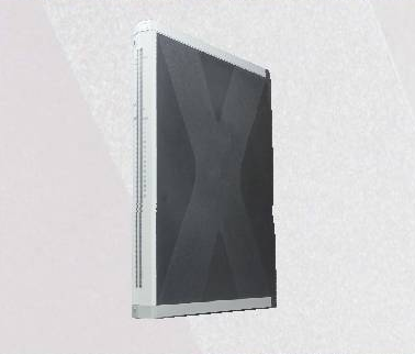
HIMA X-Di6451
Safety-Related Digital Input Module Specification
Basic Specifications
Model Number
X-Di6451
Module Type
SIL 3 Certified Digital Input Module
Input Voltage
24V DC (18-30V DC)
Input Channels
16 Digital Inputs (2/4-wire configurable)
Safety Integrity Level
SIL 3 (per IEC 61508)
Operating Temperature
-40°C to 70°C (-40°F to 158°F)
Functional Description
The HIMA X-Di6451 is a high-integrity digital input module designed for use in safety instrumented systems (SIS) and critical control applications. It is part of the HIMA X-Series safety platform, providing reliable and secure acquisition of digital signals from field devices.
The module features channel-wise diagnostics, galvanic isolation (500V AC) between channels and backplane, and redundant power supply inputs for maximum availability. It supports both 2-wire and 4-wire sensor connections, with configurable input delay times for noise suppression.
Compliant with international safety standards including IEC 61508 (SIL 3), IEC 61511, and DNV GL, the X-Di6451 is suitable for use in oil & gas, chemical, power generation, and other process industries requiring highest safety levels.
Related Series:
HIMA X-DI6401
HIMA X-DI6451
Installation Requirements
- Install only in HIMA X-Series cabinets with compatible backplane modules (X-BPxx)
- Ensure proper EMC grounding in accordance with HIMA installation manual (minimum 4mm² ground wire)
- Use twisted pair shielded cables for input wiring (shield termination at cabinet side only)
- Maintain minimum clearance of 20mm between modules for thermal management
- Perform functional safety test after installation in accordance with SIL verification procedures
- Follow torque specifications (0.8 Nm) for front connector screws to ensure vibration resistance
- Verify module identification and firmware version before commissioning

Leave a comment
Your email address will not be published. Required fields are marked *